in2TopoHyd: Initial Hydraulic Conditions Module
in2TopoHyd is a module for deriving initial hydraulic conditions for the c1TIF computation module
for a debris-flow hydrograph at a prescribed release line. The module combines the topography of the release area with
a time-dependent discharge hydrograph (Topo-Hydrograph) to calculate the corresponding flow thickness and flow velocity at the release line.
The hydraulic conditions are derived from the terrain cross section along the release line. A rating curve is calculated from the cross-sectional geometry, relating flow thickness to flow area. For each discharge value of the input hydrograph, the module determines the corresponding mean flow velocity and flow thickness. The flow thickness is then distributed over the wetted cells of the release cross section.
The resulting initial conditions contain the flow thickness as well as the velocity components in x, y and z direction for every wet cell and every hydrograph timestep.
Note
The module is still under development and the functions are not fully tested yet!
Theory
The hydraulic boundary conditions are derived in several steps.
1. Terrain cross section
The release line constists of a starting and an ending point and is first mapped to the DEM raster grid. The two release-line points are assigned to the nearest raster-cell coordinates. All DEM cells along the resulting line are then extracted. For each cross-section cell, the module stores its x and y coordinates and its terrain elevation. The distance along the cross section is calculated and used for the subsequent hydraulic calculations.
2. Levee points
Two so called levee points define the left and right top of the channel embankment which constrain the flow to the main channel. Only this part of the cross section is considered for the calculation of the flow area.
3. Rating curve
A rating curve is calculated from the terrain cross section between the levee points.
The lowest elevation within this channel section is taken as the minimum channel elevation. Starting from this elevation, the module increases the flow surface elevation in increments of dElev.
For each surface elevation, all cross-section cells below the flow surface are considered wetted. The corresponding flow area is calculated by integrating the flow thickness along the cross section.
It is subsequently used to convert the flow area required for a given discharge into a corresponding flow thickness.
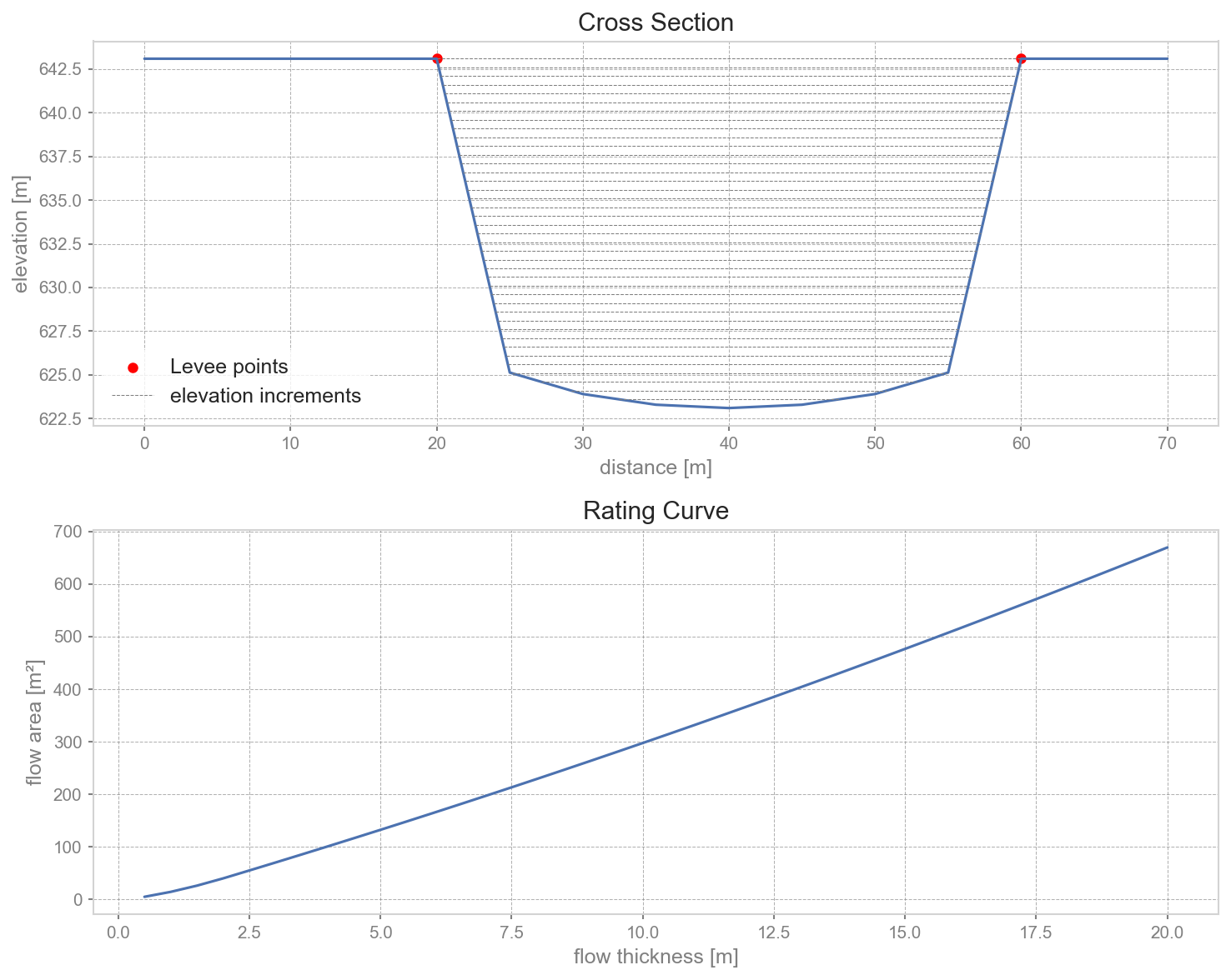
Channel cross section and corresponding rating curve
4. Flow velocity
Note
The current implementation provides the approach after [Ric99] as the only available method for calculating the mean flow velocity.
For each discharge value, the mean flow velocity is calculated. The currently implemented approach [Ric99] calculates the veloctiy [m/s] as:
where \(Q\) is the discharge [m³/s] and \(S\) is the mean channel slope [m/m] in flow direction. The slope can either be supplied through the configuration file via \(slope\) or calculated automatically. For the automatic calculation, two additional cross sections are generated in a predefined normal distance on each side of the release line. The mean elevations between the levee points of this virtual cross sections are used to estimate the slope using a central difference:
where d is the normal distance between the release line and the virtual cross section.
5. Flow area and flow thickness
Once the mean velocity is known, the required flow area \(A\) [m²] is obtained from the mass balance equation:
The required flow area is then compared with the previously calculated rating curve and the flow thickness corresponding to the required flow area is obtained by interpolation of the rating curve. If the required flow area exceeds the maximum flow area represented by the rating curve, the module stops and reports that the discharge is overtopping the debris-flow channel.
6. Distribution over the release cross section
The calculated flow thickness represents the thickness measured from the lowest point of the channel. For each timestep, the corresponding surface elevation \(Elev_{surf}\) [m] is calculated as:
All cross-section cells with an elevation below this surface are considered wet. For each wet cell, the local flow thickness is calculated as the difference between the flow surface elevation and the terrain elevation. Consequently, the resulting initial condition is spatially distributed across the cross section rather than assigning one constant thickness to every cell.
7. Flow direction
The release line is supposed to be normal to the horizontal channel flow direction.
Note
It is in the responsibility of the user to create a release line normal to the channel flow direction! Otherwise correct results cannot be guaranteed.
In a predefined normal distance the program generates two additional cross sections on each side of the release line (compare to calculation of slope). The mean elevations of this virtual cross sections are then compared to determine which of the two possible normal directions corresponds to the downslope direction.
The vertical component is obtained from the DEM surface normal. The resulting three-dimensional direction vector is multiplied by the calculated mean velocity to obtain the velocity components:
```
velocityX velocityY velocityZ ```
These components are assigned to every wet cell belonging to the respective timestep.
Input
The in2TopoHyd module requires a
digital elevation model as raster file,
a time-dependent discharge hydrograph,
a release line,
and levee points.
in2TopoHyd calculations are performed within a process directory, organized with the
folder structure described in the AvaFrame documentation.
Digital elevation model
The module uses the provided DEM in Inputs to obtain the terrain elevation along the release line.
The DEM cell size and raster origin are also used to map the release line to raster cells.
Release line
The release line is read from the Inputs/REL directory. It must contain exactly two points, representing the starting and ending point of the release line.
If a releaseScenario is specified in local_c1TIFCfg.ini, this file is used (with extension .shp). Otherwise, the module searches the REL directory for a release file.
If no unique release file can be identified, the module stops with an error.
The release line defines the terrain cross section used for the hydraulic calculations.
Levee points
The module requires exactly one point shapefile in Inputs/POINTS whose filename ends with *levee.shp.
The levee points define the lateral limits of the debris-flow channel. Each levee point is assigned to the nearest DEM cell of the release cross section.
Discharge hydrograph
The time-dependent discharge is read from the hydrograph file (.csv) in Inputs/REL.
The hydrograph must contain the columns:
timestep — timestep of the discharge value [s]
discharge — discharge value [m³/s]
The discharge values are used to derive the hydraulic conditions for every timestep of the hydrograph.
Model configuration
The model configuration is read from in2TopoHydCfg.ini. A local copy can be created and modified for individual process directories.
The available parameters are:
dElevElevation increment used to calculate the cross-sectional flow area. For low discharge values it might be necessary to decrease
dElevvelTypeMethod used to calculate the mean flow velocity.
slopeMean slope in flow direction [m/m]. If this parameter is left empty, the slope is calculated automatically from the DEM.
exportCrossSectionCellsIf set to
True, the coordinates and elevations of the cross-section cell centers are exported as a CSV file for plausibility checking.
The default parameter values are stored in in2TopoHydCfg.ini.
Output
The module creates the following output structure:
Outputs/
└── in2TopoHyd/
    ├── initCondHyd.csv
    ├── crossSectionCells.csv        (optional)
    └── Plots/
        ├── crossSection.png
        └── ratingCurve.png
Initial hydraulic conditions
The main output is initCondHyd.csv.
For every wet cross-section cell and hydrograph timestep, the file contains:
timestep — hydrograph timestep [s]
thickness — local flow thickness [m]
velocityX — x-component of flow velocity [m/s]
velocityY — y-component of flow velocity [m/s]
velocityZ — z-component of flow velocity [m/s]
x — coordinate of the wet cell
y — coordinate of the wet cell
The file therefore provides spatially distributed hydraulic initial conditions along the release line.
Cross-section cells
If exportCrossSectionCells = True, the module additionally writes crossSectionCells.csv.
The file contains:
x — coordinate
y — coordinate
elev — DEM elevation [m]
This output can be used to check whether the release line has been correctly mapped to the DEM and whether the resulting terrain cross section is plausible.
Plots
Two plots are generated for plausibility checks.
crossSection.pngShows the terrain elevation along the release cross section and the location of the levee points.
ratingCurve.pngContains both the terrain cross section with the calculated flow-surface elevation steps and the resulting relationship between flow thickness and flow area.
These plots are intended to help verify the geometric and hydraulic calculations.
To run
first go to
DebrisFrame/debrisframecopy
debrisframeCfg.initolocal_debrisframeCfg.iniand set your desired process directory namecreate a process directory with the required DEM, release line, levee points and hydrograph
copy
in2TopoHyd/in2TopoHydCfg.initoin2TopoHyd/local_in2TopoHydCfg.iniand, if desired, change the configuration settingsrun:
pixi run python runIn2TopoHyd.py
The complete workflow reads the DEM and release information, generates the release cross section, calculates the rating curve,
derives the hydraulic conditions from the discharge hydrograph and writes the resulting initial conditions to Outputs/in2TopoHyd/initCondHyd.csv.